Plug Diagram Labelled : iPad charger teardown: inside Apple's charger and a risky phony / Spark plug diagram | spark plug diagram.. The change of a solid directly into vapour on heating and of vapour into solid on cooling is known as sublimation. In a plug, the blue neutral wire goes to the left, the brown live wire to the right and the green and yellow striped earth wire to the top. Connection diagram plug x3, connection diagram plug x4. A simple diagram of pump casing with. After you've studied all the pieces of the compound microscope, it's time to put your brain to the test.
You can now define a path between two intersections, and place a node halfway between the intersections using node pos=0.5 {<label>} in the path. But, it does tend to become more complex. It uses impeller to increase kinetic energy due to rotation of liquid passing through it followed with conversion into pressure in casing. Using the terms listed below, label the microscope diagram. A piping and instrumentation diagram (p&id) is a detailed diagram in the process industry which shows the piping and process equipment together with the instrumentation and control devices.
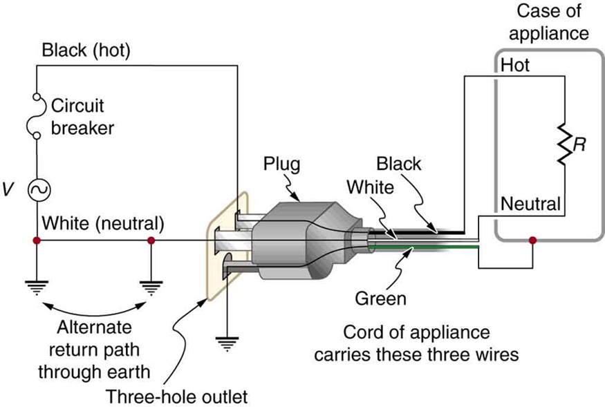
23.8 Electrical Safety: Systems and Devices - College Physics: OpenStax from pressbooks.bccampus.ca I only see examples to populate / select data and nothing to draw any diagrams. First and foremost, we have a labeled microscope diagram, available in both black and white and color. Labeled diagram of the human kidney. › label and label location. What i plot is just the numbers of elements in common. What i want is to print the real a,b,c,. Connection diagram plug x3, connection diagram plug x4. The best new vst plugins are released every month and we are constantly updating our list.
The glow plug relay is a simple automotive type relay similar to that which is used for starter motors.
The plug coming off of the trans has two pink wires and two yellow and black wires and a white wire that i need to figure out where to connect them. Ielts listening label the plan 2. Have created a rating for you best 43 vocal processing vst plugins 2021. After you've studied all the pieces of the compound microscope, it's time to put your brain to the test. I wrote the following code to create a venn diagram to show the intersection of 3 sets. <br> <img src an electric circuit consisting of a 0.5m long nichrome wire xy, an ammeter, a voltmeter, four cells of `1.5v` each and a plug key was set up. Useful as a study guide for learning the anatomy of a microscope diagram unlabeled. A simple diagram of pump casing with. And continue with the masking tape to hold harness in its stock shape. What i want is to print the real a,b,c,. When including a plc in the ladder diagram still remains. The ultimate aim of pump is to develop pressure and for this either volute type or diffusers with ring type pump casing are used. But, it does tend to become more complex.
Connection diagram plug x3, connection diagram plug x4. › label and label location. I wrote the following code to create a venn diagram to show the intersection of 3 sets. The glow plug relay is a simple automotive type relay similar to that which is used for starter motors. <br> circuit diagram for ohm's law:
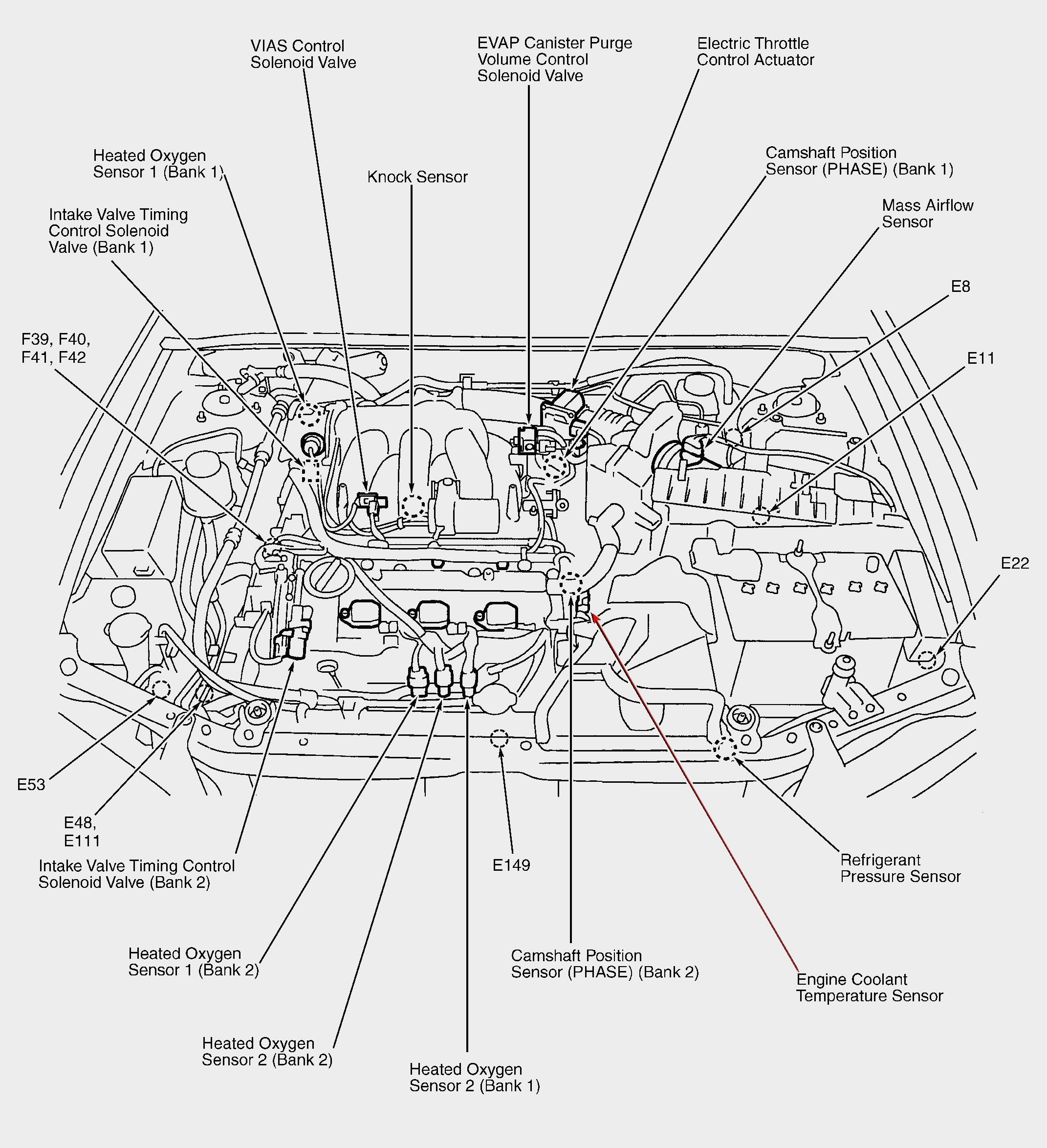
Labelled Diagram Of Car Parts | My Wiring DIagram from detoxicrecenze.com What i plot is just the numbers of elements in common. <br> circuit diagram for ohm's law: The glow plug relay is a simple automotive type relay similar to that which is used for starter motors. The ultimate aim of pump is to develop pressure and for this either volute type or diffusers with ring type pump casing are used. After you've studied all the pieces of the compound microscope, it's time to put your brain to the test. Drag and drop the pins to their correct place on the image. Choose the right electrical plug diagram that lasts longer and serves your needs. First and foremost, we have a labeled microscope diagram, available in both black and white and color.
Labeled diagram of the human kidney.
First and foremost, we have a labeled microscope diagram, available in both black and white and color. The change of a solid directly into vapour on heating and of vapour into solid on cooling is known as sublimation. That diagram helps a lot as far as finding out which pin/pcm the wire goes to without having to pull up the schematics & all that other stuff. The glow plug system on the 7.3l idi consists of a glow plug relay, glow plug controller, and 8 individual glow plugs. Learn vocabulary, terms and more with flashcards, games and other study tools. Connection diagram plug x3, connection diagram plug x4. After following steps removing yellow highlighted wires from pcm connectors, and labeling blue highlighted wires, you are left with this. <br> <img src an electric circuit consisting of a 0.5m long nichrome wire xy, an ammeter, a voltmeter, four cells of `1.5v` each and a plug key was set up. The glow plug relay is a simple automotive type relay similar to that which is used for starter motors. Learn more about the options already. In a plug, the blue neutral wire goes to the left, the brown live wire to the right and the green and yellow striped earth wire to the top. Have created a rating for you best 43 vocal processing vst plugins 2021. The ultimate aim of pump is to develop pressure and for this either volute type or diffusers with ring type pump casing are used.
Spark plug diagram | spark plug diagram. I wrote the following code to create a venn diagram to show the intersection of 3 sets. The glow plug system on the 7.3l idi consists of a glow plug relay, glow plug controller, and 8 individual glow plugs. Come in and write your opinion about the rating! The glow plug relay is a simple automotive type relay similar to that which is used for starter motors.
Draw a Labelled Diagram with Necessary Switch, Regulator Etc. to Connect a Bulb, a Plug Socket ... from www.shaalaa.com The glow plug system on the 7.3l idi consists of a glow plug relay, glow plug controller, and 8 individual glow plugs. On naturally aspirated engines, the glow plug controller is located at the rear. You can now define a path between two intersections, and place a node halfway between the intersections using node pos=0.5 {<label>} in the path. The glow plug relay is a simple automotive type relay similar to that which is used for starter motors. That diagram helps a lot as far as finding out which pin/pcm the wire goes to without having to pull up the schematics & all that other stuff. <br> <img src an electric circuit consisting of a 0.5m long nichrome wire xy, an ammeter, a voltmeter, four cells of `1.5v` each and a plug key was set up. Learn vocabulary, terms and more with flashcards, games and other study tools. After following steps removing yellow highlighted wires from pcm connectors, and labeling blue highlighted wires, you are left with this.
On naturally aspirated engines, the glow plug controller is located at the rear.
In a plug, the blue neutral wire goes to the left, the brown live wire to the right and the green and yellow striped earth wire to the top. Includes guides for 7 pin, 6pin, 5 pin, 12 pin, 13 pin, pin and heavy duty round plugs and sockets. Spark plug diagram | spark plug diagram. The fuse fits next to the live wire. Gateway a2 unit 3 body parts. › label and label location. People also love these ideas. <br> (i) draw a diagram of this electric circuit to study. Using the terms listed below, label the microscope diagram. Figure 5 below shows a schematic diagram for a plc based motor control system, similar to the previous motor control example. Drag and drop the pins to their correct place on the image. Where does each wire go? Come in and write your opinion about the rating!
The glow plug relay is a simple automotive type relay similar to that which is used for starter motors plug diagram. You can now define a path between two intersections, and place a node halfway between the intersections using node pos=0.5 {<label>} in the path.

0 Comments:
Posting Komentar